Two Wheel Odometry
Ivan Chen
This project was done as the final project of CPET-253 (Microcontroller Systems) at RIT.
Project Description
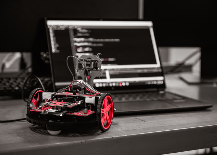
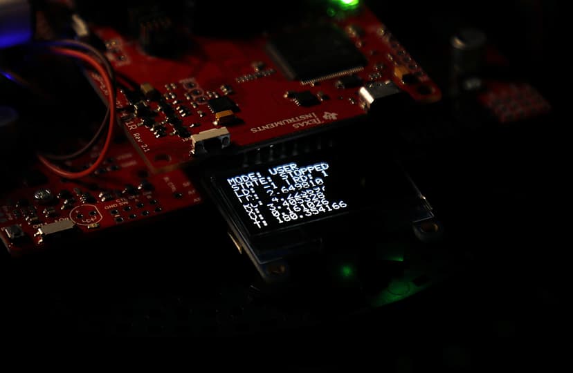
This project aims to provide the distance the robot's left and right wheels have traveled using rotary Hall Effect quadrature encoders. This lets us track the position and orientation of the robot over time, known as odometry, without an Inertial Measurement Unit (IMU). We will use this information about the robot's position to drive the robot towards its starting point (a "homing function"). The robot will also be able to wander around a room while avoiding obstacles using ultrasonic sensors, all while continuously tracking its position (a "wandering function"). The robot will be controlled using a mobile smartphone, which will communicate with the robot using Bluetooth. Two finite state machines control the mode of the robot, and the state of its motors. Information about the current state of the robot is displayed on the LED screen on the robot.
The initial project proposal can be found here. MD5: ef0ed11e0038c1e68c848de2b34b836f
The code for this project can be found here.
Obstacles Faced
There were a couple obstacles that I had faced while working on this project. First, I had to figure out how encoders on this robot were connected to the board, then figure out how to read the encoder values using hardware interrupts. After being able to properly read the direction and accumulate counts of the encoders, I moved onto working on homing and wandering functions. I tried multiple ways to do the homing, but the inaccuracy of the robot's odometry position and rotation drifting over time meant that this was more complicated than expected. In the end, I was able to figure out a simpler way to do the homing, and also had to tune the wheel speeds, rotation parameters, and tolerances in "completing" the homing process, which took multiple hours to get fairly consistent.
Testing and Verification
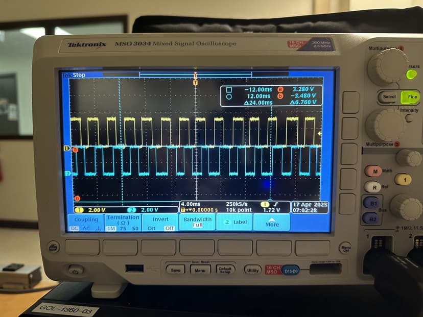
After finding what pins the output of the encoder is on, I used the oscilloscope to verify the waveforms and see what they look like. After writing the code, I was able to test each part of the code individually: confirming the Bluetooth connection works and I can send commands to the robot, checking that the state machines and switching between modes and states worked, messing with the encoders and checking if it was reading the values and direction properly and converting to feet properly, checking if the odometry is accurate (it is not very accurate) enough, and then starting to test the special functions.
When testing the wandering function, I let the robot drive around the room, checking if there was weird behavior and edge cases that was not considered in the code. The wandering function worked fairly well, and I moved onto the homing function. Here, I had first manually moved the robot, first only forward, then only backwards, then with turns, and seeing if the homing calculation would make the robot face the correct direction, then drive towards it. I tested various tolerances for the end condition of the homing and also the tolerances for the rotation towards the goal, and had to settle on fairly large tolerances to accomodate the innacuracies of the robot.
Possible Improvements
My project currently suffers from drift over time due to small inaccuracies accumulating, especially in tracking the rotation of the robot. An improvement could be integrating an Inertial Measurement Unit (IMU) or optical flow sensor to provide better localization through sensor fusion.
A more robust approach to the homing function could use PID control to more precisely rotate to the proper angle and also driving to the origin point. Some sort of path planning might also improve the homing functionality.
Including obstacle avoidance using the ultrasonic sensors and figuring out how to get around the obstacle in the homing feature would also be nice.
Technical Information
Encoders
Hall effect quadrature encoders work by using a rotating disc with evenly spaced magnets. As the disc rotates, these magnets pass over two Hall effect sensors, which are positioned slightly apart. Each sensor outputs a signal that switches between high and low states as the magnets pass by. Because the sensors are offset, their signals are out of phase, creating two pulse lines (A and B) offset by 90 degrees. By monitoring the sequence of these pulses, we can determine the direction of rotation. The number of pulses also tells us how far the wheel has rotated.
To capture these pulses, we use hardware interrupts that read both lines when triggered, and this figures out the direction the motor is being driven in. Given that A is BIT1 and B is BIT0, reading 01 would mean going in one direction, and reading 10 would mean going in the opposite direction. We have a left and right encoder, so we must keep track of two encoders counts.
In this case, the wheels had a diameter of 2.75 inches, a gear ratio of 60:1 between the motor shaft and wheel shaft and 12 counts per motor shaft rotation. This means that to convert actual distance traveled (in feet) from raw encoder counts, which is counted on both the rising and falling edges, we must do a unit conversion. This unit conversion is
dist_in_ft = (counts / (60.0 * 12.0)) * 2.0 * (2.75 / 12.0) * M_PI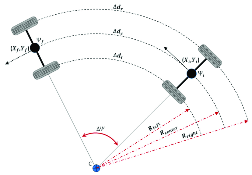
Odometry
Two-wheel odometry is a method of estimating a robot's position and orientation by using the data from two wheels. By tracking the rotation of each wheel, we can determine how far the robot has traveled and how much it has turned. This information is then used to update the robot's estimated position and orientation in a process called pose estimation.
const double REF_TO_WHEEL_DIST = 0.25; // feet

struct data {
  double x;
  double y;
  double theta;
};

struct data current_pose, prev_pose;

void update_pose (double delta_left, double delta_right) {
  double delta_dist = (delta_right + delta_left) / 2;
  double delta_theta = (delta_right - delta_left) / (2 * REF_TO_WHEEL_DIST);

  current_pose.x += delta_dist * cos(current_pose.theta + delta_theta / 2);
  current_pose.y += delta_dist * sin(current_pose.theta + delta_theta / 2);
  current_pose.theta += delta_theta;

  while (current_pose.theta > 2 * M_PI) current_pose.theta -= 2 * M_PI;
  while (current_pose.theta < 0) current_pose.theta += 2 * M_PI;
}
delta_left and delta_right are given to the function as the current encoder count minus the previous encoder count. A more in-depth explanation of how two wheel odometry kinematics works can be found here.

Wandering Function
The wandering function utilizes the ultrasonic sensor on the robot, which is mounted on a servo motor, to wander around a room. The robot will always try to drive forwards, but will continuously check if an obstacle is detected 20cm in front of it. If an obstacle is detected, the robot will immediately stop driving forwards, and go through a check of the left and right sides of the robot to identify which direction is free for it to move to. It triggers the servo to look left, then capture the distance to any objects to the left, then looks right to again capture the distance to any objects to the left. If nothing is detected in one direction, but something is detected in the other, it will trigger the robot to rotate 90 degrees in the free direction and continue driving forward. The robot defaults to rotating and driving left if both sides are free. This whole process will continue to run until the user stops the robot by changing modes back to USER mode.

Homing Function
The homing function works by utilizing the position and rotation values calculated by the robot as it operates and drives around. When the homing function is triggered by the user, the robot first stops, then utilizes its current position to calculate a desired heading to aim at the origin (0, 0) where it started driving from. This calculation looks like
double normalize_angle_0_to_2pi(double angle) {
  angle = fmod(angle, 2 * M_PI);
  if (angle < 0)
    angle += 2 * M_PI;
  return angle;
}

double calculate_target_angle(double x_r, double y_r, double theta_r, double x_t, double y_t) {
  double dx = x_t - x_r;
  double dy = y_t - y_r;

  double theta_target = atan2(dy, dx);
  double theta_relative = theta_target - theta_r;

  return normalize_angle_0_to_2pi(theta_relative);
}
After this calculation, we utilize a function to rotate the robot in place to this angle within a certain tolerance.
case s_HOMING: {
  if (isNewState) {
    left_start = left_counts;
    right_start = right_counts;
    target_theta_deg = radToDeg(calculate_target_angle(current_pose.x, current_pose.y, current_pose.theta, 0, 0));
    turning = true;
    hasHomedAngle = false;
    Motor_Right(14999, 13999);
  }

  if (hasCompletedTurn(left_counts - left_start, right_counts - right_start, target_theta_deg * (180.0 / 90.0))) {
    Motor_Stop();
    Clock_Delay1ms(1000);
    turning = false;
    hasHomedAngle = true;
    state = s_FORWARD;
  }
  break;
}
Finally, the robot drives forward until it reaches within a 0.75 foot radius around the origin, at which point the robot stops. This high tolerance was necessary since the accuracy of the robot's driving and tracking is not very good.
Bluetooth, Controls, and FSMs
The robot's operation is controlled using a mixture of hardware interrupts, which updates the encoder counts, and Finite State Machines (FSMs). This robot features two FSMs, one that controls the mode it is in, and another that controls the state of the motors. There are 3 modes, m_USER mode, m_HOMING mode, and m_WANDER mode. There are 6 motor states, s_STOP, s_FORWARD, s_BACKWARD, s_ROT_L_90 (rotates 90 degrees to the left), s_ROT_R_90 (rotates 90 degrees to the right), and HOMING (points robot at origin).
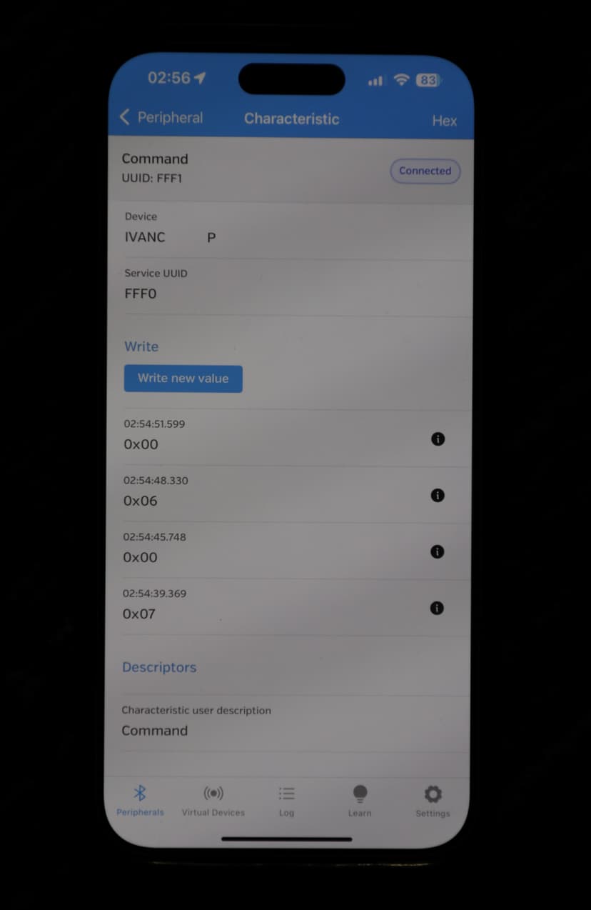
This robot is controllable using Bluetooth from a mobile smartphone. The user is able to change the modes and states the robot is in by sending an integer to the robot. The different commands sendable to the robot are shown below.
switch (command) {
  case 0: {state = s_STOP; break;}
  case 1: {state = s_FORWARD; break;}
  case 2: {state = s_BACKWARD; break;}
  case 3: {state = s_ROT_L_90; break;}
  case 4: {state = s_ROT_R_90; break;}
  case 5: {state = s_ROT_180; break;}
  case 6: {mode = m_HOMING; break;}
  case 7: {mode = m_WANDER; break;}
  case 8: {state = s_STOP; current_pose.x = 0; current_pose.y = 0; current_pose.theta = 0; left_counts = 0; right_counts = 0; break;}
  default: {state = s_STOP; break;}
}